High End Systems High End LCD Controller for Studio Color User Manual
Browse online or download User Manual for Supplementary music equipment High End Systems High End LCD Controller for Studio Color. High End Systems High End LCD Controller for Studio Color User's Manual
- Page / 272
- Table of contents
- BOOKMARKS
- Studio Color 1
- International Sales 3
- Trademarks 3
- Declaration of Conformity 4
- Important Safety Information 5
- Warranty and Conditions 6
- Limited Warranty 7
- Freight 8
- Table Of Contents 10
- Chapter 4 Basic Programming 11
- Chapter 5 Using the Menus 11
- Table Of Figures 13
- Table of Tables 15
- Introduction 17
- Features 18
- About This Manual 20
- Getting Help 22
- Chapter 1 23
- Preparing to Use Your 23
- LCD Controller 23
- Unpacking Your Controller 24
- Specifications 25
- Safety Standards 26
- Cables and Connectors 27
- Optional Accessories 28
- Replacing the Fuse 31
- Power Cord Cap 32
- EARTHED 33
- Chapter 2 35
- Setting Up Your Controller 35
- Rear Panel Descriptions 36
- Setting the Switches 38
- Connecting Fixtures 43
- Setting A Fixture Number 45
- Selecting Fixture Numbering 47
- Cables and Terminators 48
- Table 2-1. XLR Cable Pinouts 49
- Terminators 50
- Connection Rules 50
- Examples 51
- Master and Slave Controllers 54
- Master (out) 55
- Slave (in) 55
- MIDI In and Out Ports 56
- Other Connectors 57
- Rack Mounting the Controller 59
- Powering On the Controller 60
- Standby key 61
- Power key switch 61
- Chapter 3 63
- Overview of Controller 63
- Operation 63
- Programming Hints 64
- Beam Shaping 65
- Front Panel Descriptions 66
- Not used Not used Not used 70
- Not used 70
- Gate Key 71
- Red, Green and Blue Keys 71
- Using the Construct Keys 72
- Lens 1 Key 73
- MSpeed Key 74
- Xfade Key 76
- Color Key 77
- Lens 2 Key 78
- Mode Key 79
- Position Key (POS) 81
- Setting CSpeed 83
- )* 84
- Chapter 4 85
- Basic Programming 85
- Programming Overview 86
- Programming Guided Tour 88
- Recording Page 2 89
- Recording Page 3 90
- Recording Page 4 90
- Creating a Loop 91
- Recording a Preset 92
- Creating a Program 94
- Step 3: Press the Select Key 95
- Step 5: Edit Constructs 95
- Where To Go From Here 96
- Page Copy 97
- Block Copy (and Reverse) 100
- and 101
- #> -#> 101
- #+ -#+5 101
- Delay setting 102
- Preset Programming 103
- Using Preset Banking 104
- Recording a One-Page Preset 105
- Recording a Loop as a Preset 106
- Preset Playback 107
- Things to Remember 108
- Viewing and Editing Programs 109
- Viewing Fixtures 109
- Erasing Pages 111
- Master Dim 112
- Homing Fixtures 113
- Chapter 5 115
- Using the Menus 115
- Submasters 116
- Function 116
- Overview 117
- Navigating the Menus 118
- Menu Movement Keys 119
- Moving Through Menu Levels 119
- Selecting Options 120
- Multi-Page Menus 121
- Selecting MSC or LSC 122
- Setting the Device ID 123
- All-Memory Playback 125
- Locking/Unlocking Memory 126
- Locking/Unlocking a Fixture 127
- Erasing All Memory 128
- <Menu> 129
- <Down> 129
- <Right> 129
- <Up> 129
- Studio Color LCD Controller 130
- Chapter 6 131
- Advanced Programming 131
- Who Should Use this Chapter 132
- Using Position Presets 133
- Recording Position Presets 134
- Recalling Position Presets 134
- Address Parameter Copy 135
- Edit/Copy 136
- 9 :#/-! -# ' 138
- User Key Macros 139
- Erasing a Single User Key 142
- Accessing Default Definitions 143
- Erasing All User Keys 144
- Analog Inputs Ports 145
- Remote Page Access 146
- Remote Preset Access 148
- Using Binary Preset Access 151
- Binary "819" 153
- Selecting a Submaster Mode 154
- 1 ;:4+$2.%JK@8+5+++$/ 155
- Audio Input Playback 157
- Varying the Audio Sensitivity 158
- Random Advance 159
- Live Control of Auto Playback 159
- Remote Enable 160
- Lightwave Control Center 161
- Chapter 7 163
- External Memory Storage 163
- Personal Computer Options 165
- NiCad Battery Protection 165
- RAM Card: Memory 166
- RAM Card: Memory 167
- RAM Card: O/S 170
- RAM Card: O/S 171
- )/3;N N 172
- MEMORY CARD 174
- Male DB25 Connector 175
- Male DB9 Connector 175
- IBM-Compatible 176
- Initial Setup 177
- Computer 179
- D);$2$ 181
- Computer to Controller 182
- )(;$2$ 184
- Verifying the Transfer 185
- Macintosh-to-Modem cable 186
- Setting Up the Software 187
- Controller to Computer 188
- Macintosh 189
- *#8-# 191
- Crossloading 192
- (Male DB9)(Female DB9) 193
- 193
- Serial Cable 193
- Crossload Procedure 194
- Glossary 197
- Delay Time 199
- Dichroic filters 199
- Fixture Number 201
- Lightwave Show Control 201
- Luminaire 202
- MIDI Show Control (MSC) 203
- Mirror Mode 203
- RAM Card 206
- Sequence 206
- Serial Data Distributor 206
- Show Control 207
- Studio Color Upload Module 208
- Submaster 208
- Tip/Ring connector 208
- Tip/Ring/Sleeve connector 208
- Twelve-Level Preset Access 209
- Un-initialized Page 209
- User-Defined Keys 209
- User Memory 209
- Appendix A 211
- Binary Access Table 211
- Appendix B 247
- Construct Parameters 247
- Appendix C 251
- Pinouts and Wiring 251
- Diagrams 251
- Connector Pin Numbering 252
- Straight-Through 253
- Null Modem 253
- Appendix D 255
- Important Safety 255
- Information 255
- Appendice D 256
- Important: Informations De 256
- Sécurité 256
- Anhang D 257
- Wichtige 257
- Sicherheitshinweise 257
- Apéndice D 258
- Información Importante De 258
- Seguridad 258
- Appendiks D 260
- Vigtig Sikkerhedsin 260
- <Audio> 261
- <Blue> 261
- ) 7-5 262
- 7-5, 7-9 262
- O) 263
- ) 6-6 263
- )* 3-21, 3-22 264
- <Mode> 266
- <MSpeed> 266
- -//3; 7-9 267
- <Rate> 268
- <Record> 268
- <Red> 268
- <Select> 268
- <Standby> 269
- ) 5-9 271
- <XFade> 272
Summary of Contents
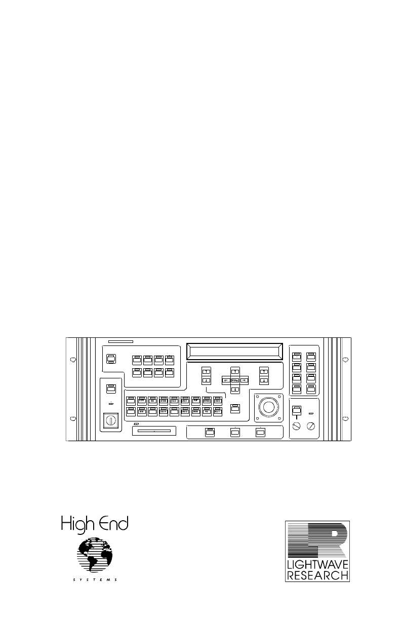
p/n 60600079 Version 1.0LCD Controller for Studio ColorUser ManualADVANCELIGHTWAVEaudioleveleraserecordselecthomepagecursorconstructPAGEMEMORYINTENSIT
Studio Color LCD ControllerTable Of ContentsixTable Of ContentsIntroductionFeatures...
4-16 Block Copy (and Reverse)Studio Color LCD Controller3. Press the <Erase> key. The LCD display appears as shown below:4. Press the <Eras
Studio Color LCD ControllerBlock Copy (and Reverse)4-1743. Press the <Auto> key, located to the right of the joystick. The LCD display then app
4-18 Setting Rate and Delay TimeStudio Color LCD ControllerSetting Rate and Delay TimeBefore continuing, make sure the controller is ready for progra
Studio Color LCD ControllerPreset Programming4-194Varying the Delay TimeThe Delay (time) construct sets the amount of time you want the controller to
4-20 Preset ProgrammingStudio Color LCD ControllerNotes (1) Audio advance is independent of the presets. For more information about audio triggering
Studio Color LCD ControllerPreset Programming4-214Recording a One-Page Preset 1. Use the Construct and Page <Up> and <Down> arrow keys to
4-22 Preset ProgrammingStudio Color LCD ControllerRecording a Loop as a PresetStart the loop running, then assign the entire loop to one of the Prese
Studio Color LCD ControllerPreset Playback4-234• Advance settings: • Random, Audio 1, Audio 2: see “Audio Input Playback” on page 6-27.• Auto: see
4-24 Preset PlaybackStudio Color LCD ControllerThings to Remember• To change to another preset at any time, switch to the bank containing the preset
Studio Color LCD ControllerViewing and Editing Programs4-254Viewing and Editing ProgramsOnce your pages are programmed, you can view or edit the pages
xTable Of ContentsStudio Color LCD ControllerChapter 4 Basic ProgrammingProgramming Overview... 4-2
4-26 Viewing FixturesStudio Color LCD Controller4. A summary of all constructs and parameters for that fixture number appears, similar to the one sho
Studio Color LCD ControllerErasing Pages4-274Erasing PagesYou may want to erase a page when there are undesirable or old pages in memory. It is often
4-28 Master DimStudio Color LCD ControllerMaster DimThe sample LCD display below shows a value of 88 for Intensity (also called master dim). The val
Studio Color LCD ControllerHoming Fixtures4-294Homing FixturesHoming a fixture causes its shutter to close, its lamp to strike (if off), and for all w
4-30 Homing FixturesStudio Color LCD Controller
Studio Color LCD Controller 5-15Chapter 5Using the MenusOverview... 5-2Naviga
5-2 OverviewStudio Color LCD ControllerOverviewFigure 5-1 shows an overall view of the menu system:Figure 5-1. The Studio Color LCD controller’s men
Studio Color LCD ControllerOverview5-35• Help: On-screen help for all Main menu options. • Backup: Options for transferring controller memory to a
5-4 Navigating the MenusStudio Color LCD ControllerNavigating the MenusThis section explains how to use the menu system. More information is contain
Studio Color LCD ControllerNavigating the Menus5-55the Main menu.You use the Construct, Cursor and Page arrow keys to navigate in the menu system. Th
Studio Color LCD ControllerTable Of Contentsxi Chapter 6 Advanced ProgrammingIntended Audience...
5-6 Navigating the MenusStudio Color LCD Controllerbelow:Pressing the Cursor <Down> arrow key again has no effect, since there are no menu item
Studio Color LCD ControllerNavigating the Menus5-75Multi-Page MenusSome of the Help menus are more than one page long. You use the Construct <Up&g
5-8 Selecting MSC or LSCStudio Color LCD ControllerSelecting MSC or LSCMIDI Show Control (MSC) and Lightwave Show Control (LSC) are two different pro
Studio Color LCD ControllerSelecting MSC or LSC5-953. Press the Cursor <Down> arrow key to display the menu options shown below: 4. Use the Curs
5-10 Selecting MSC or LSCStudio Color LCD ControllerIf you are continuing from the previous section, begin with Step 3.1. Enter the menu system by pr
Studio Color LCD ControllerAll-Memory Playback5-115All-Memory PlaybackThis section describes how to auto advance or random advance through all 99 page
5-12 Locking/Unlocking MemoryStudio Color LCD ControllerLocking/Unlocking MemoryUse the memory lock function to lock out all pages in a memory so the
Studio Color LCD ControllerLocking/Unlocking a Fixture5-135Locking/Unlocking a FixtureThis feature temporarily removes a fixture from all pages. This
5-14 Erasing All MemoryStudio Color LCD ControllerErasing All MemoryThe Erase All function provides a quick way to clear all programming (all unlocke
Studio Color LCD ControllerSetting the Backlight Intensity5-155Setting the Backlight IntensityYou can set the intensity (brightness) of the LCD displa
xiiTable Of FiguresStudio Color LCD ControllerTable Of FiguresFigure 1-1. Location of the controller’s voltage selectionswitch and fuse. ...
5-16 Setting the Backlight IntensityStudio Color LCD Controller
Studio Color LCD Controller 6-16Chapter 6 Advanced ProgrammingWho Should Use this Chapter... 6-2Using Positio
6-2 Who Should Use this ChapterStudio Color LCD ControllerWho Should Use this ChapterThis chapter is intended for users already familiar with control
Studio Color LCD ControllerUsing Position Presets6-36Using Position PresetsThe controller has a time-saving feature called position preset (also calle
6-4 Using Position PresetsStudio Color LCD ControllerThe full set of 99 position presets is available for all fixtures connected to the controller.
Studio Color LCD ControllerAddress Parameter Copy6-564. Press the <POS> (Position) construct key and use the Construct <Up> and <Down&g
6-6 Address Parameter CopyStudio Color LCD ControllerEdit/CopyThe Edit/Copy feature has two options:• “Share all Constructs until selected” (the defa
Studio Color LCD ControllerAddress Parameter Copy6-76Copy Parameters to Another Fixture, Same Page1. Select the memory and page containing the fixture
6-8 Address Parameter CopyStudio Color LCD ControllerCopy Parameters From One Page to Another Page1. Select the memory and page containing the fixtur
Studio Color LCD ControllerUser Key Macros6-96User Key MacrosThe controller has eight front panel User keys that can be used to store custom macros (a
Studio Color LCD ControllerTable Of FiguresxiiiFigure 2-17. Locations of the other connectors on the controller’s rear panel...
6-10 User Key MacrosStudio Color LCD Controller3. The selected User key’s LED flashes, indicating you are recording. Every keystroke you make from n
Studio Color LCD ControllerUser Key Macros6-1166. Select the memory and page (destination) you want to copy the contents of the current page to: • Pre
6-12 User Key MacrosStudio Color LCD ControllerErasing a Single User KeyTo erase one of the User keys, record a zero-keystroke macro over the old mac
Studio Color LCD ControllerUser Key Macros6-136Accessing Default DefinitionsThis section describes how to access the six default User key definitions
6-14 User Key MacrosStudio Color LCD ControllerErasing All User KeysErasing all User keys deletes any custom macros you have programmed and returns t
Studio Color LCD ControllerAnalog Inputs Ports6-156Analog Inputs PortsYou can attach an analog controller to the two Analog Inputs ports located on th
6-16 Remote Page AccessStudio Color LCD ControllerRemote Page AccessThe remote page access feature allows you to remotely play back pages from the me
Studio Color LCD ControllerRemote Page Access6-176c. Channels 10, 11, and 12 when used in combination with other channels become function keys as expl
6-18 Remote Preset AccessStudio Color LCD ControllerRemote Preset AccessTwelve-level preset access and binary preset access allow you to do one or bo
Studio Color LCD ControllerRemote Preset Access6-196Using Twelve-Level Preset AccessTwelve-level preset access allows you to record and play back up t
xivTable of TablesStudio Color LCD ControllerFigure 7-1. Slide the write-protect bar to the right to allow the RAM card to accept data, or move it to
6-20 Remote Preset AccessStudio Color LCD Controlleraudio 1 and 2 advance (page 6-27), color modulate (page 6-27) and dim modulate (page 6-27) as nee
Studio Color LCD ControllerRemote Preset Access6-216Using Binary Preset AccessBinary preset access allows you to record and play back up to 1023 prese
6-22 Remote Preset AccessStudio Color LCD Controllerauto advance (page 4-18), audio 1 and 2 advance (page 6-27), color modulate (page 6-27), and dim
Studio Color LCD ControllerSubmasters6-236Playing Back in Binary Preset AccessAppendix A lists all of the binary preset access combinations. The sele
6-24 SubmastersStudio Color LCD ControllerSelecting a Submaster ModeThere are two submaster modes: Proportional level or Remote level.• Proportional
Studio Color LCD ControllerSubmasters6-256Assigning a Channel for Master Dim This section explains how to use a submaster as the “master dim controlle
6-26 SubmastersStudio Color LCD ControllerYou can skip the first two steps below if you are continuing from the previous section.1. Select ;
Studio Color LCD ControllerAudio Input Playback6-276Audio Input PlaybackYou can use an external stereo source to control playback through any or all f
6-28 Audio Input PlaybackStudio Color LCD ControllerVarying the Audio SensitivityAdjust the sensitivity of the audio advance modes to the audio signa
Studio Color LCD ControllerRandom Advance6-296Random AdvanceRandom advance when used with auto advance, manual advance or audio advance (and optionall
xvTable of TablesStudio Color LCD Controller
6-30 Remote EnableStudio Color LCD Controller3. To return from “live” control press the <Select> key. The Select LED stops flashing and the se
Studio Color LCD ControllerLightwave Control Center6-316Lightwave Control CenterSelecting Lightwave Show Control (LSC) as described in the section tit
6-32 Lightwave Control CenterStudio Color LCD Controller
Studio Color LCD Controller 7-17Chapter 7External Memory Storage and TransferOverview...
7-2OverviewStudio Color LCD ControllerOverviewThis chapter describes options for backing up and restoring the controller’s internal memory and operati
Studio Color LCD ControllerOverview 7-37Personal Computer OptionsIn addition to backing up and restoring controller memory using a RAM card, you can a
7-4RAM Card: MemoryStudio Color LCD ControllerRAM Card: MemoryThis section explains how to:• Copy all of the controller’s internal memory to a RAM ca
Studio Color LCD ControllerRAM Card: Memory 7-572. Press the <Menu> key to enter the menu system.3. Use the Cursor <Right> and <Left>
7-6RAM Card: MemoryStudio Color LCD Controller6. If you want to cancel the backup operation at this time press the <Select> key or the Cursor &l
Studio Color LCD ControllerRAM Card: Memory 7-773. Use the Cursor <Right> and <Left> arrow keys to select ? from the Main menu, as sh
Studio Color LCD ControllerFeaturesIntro-1IntroductionCongratulations on your purchase of the Lightwave Research® Liquid Crystal Display (LCD) control
7-8RAM Card: O/SStudio Color LCD ControllerRAM Card: O/SThis section explains how to back up, replace or update the controller’s operating system fro
Studio Color LCD ControllerRAM Card: O/S 7-974. Press the Cursor <Down> arrow key to view the menu options, then select/3;,, as shown belo
7-10RAM Card: O/SStudio Color LCD ControllerRestoring the Operating System from a RAM CardThis section describes how to install an operating system fr
Studio Color LCD ControllerRAM Card: O/S 7-1177. Press the <Erase> key again to continue, or press the <Select> key to cancel. If you pre
7-12RAM Card: Write-ProtectionStudio Color LCD ControllerRAM Card: Write-ProtectionAfter backing up either the operating system or memory to the RAM
Studio Color LCD ControllerIBM-Compatible 7-137IBM-CompatibleThis section describes how to back up and restore the controller’s pages, memories and pr
7-14IBM-CompatibleStudio Color LCD ControllerYou can use a DB9 to DB25 adapter if the female end of your serial cable does not match your computer’s s
Studio Color LCD ControllerIBM-Compatible 7-157Initial SetupYou must follow the procedure below backing up controller memory to a personal computer, o
7-16IBM-CompatibleStudio Color LCD Controller6. The menu shows the currently-selected option in reverse video; in Figure 7-3, the selected option is H
Studio Color LCD ControllerIBM-Compatible 7-17710. Now see one of the following sections:• “Backing Up (Downloading) Memory to the Computer” on page 7
Intro-2FeaturesStudio Color LCD Controller• 891 pages (scenes)•9 memories• Up to 1024 programmable presets from the front panel through the use of pre
7-18IBM-CompatibleStudio Color LCD Controller2. The next menu gives you the following options which are available throughout the rest of the procedure
Studio Color LCD ControllerIBM-Compatible 7-1976. Press and hold the <Record> key (about 10 seconds) on the controller’s front panel until the L
7-20IBM-CompatibleStudio Color LCD ControllerVerifying the TransferMake sure the memory was backed up properly using either Windows File Manager (or E
Studio Color LCD ControllerIBM-Compatible 7-2171. Use your computer’s <Up> and <Down> arrow keys to select Computer->Controller from th
7-22IBM-CompatibleStudio Color LCD Controller3. First, select the drive where the backup file is located. The current drive is displayed at the top o
Studio Color LCD ControllerIBM-Compatible 7-2379. A message is displayed on the Lightwave Backup software menu when the transfer is complete. Press
7-24MacintoshStudio Color LCD ControllerMacintoshThis section describes how to back up and restore the controller’s pages, memories and presets using
Studio Color LCD ControllerMacintosh 7-2573. Connect the Mac-to-modem cable to the DB25 end of the adapter. See Figure 7-7:Figure 7-7. Connecting a
7-26MacintoshStudio Color LCD Controllerdescribed in the section titled “Connecting the Computer and Controller” on page 7-24.1. Start White Knight.
Studio Color LCD ControllerMacintosh 7-2771. Toggle the <Standby> key on the controller’s front panel until the Standby LED turns ON.2. Press an
Studio Color LCD ControllerFeaturesIntro-3• Shutter strobing• Color mixing•Flip• Frost effect• Wide angle effectPlayback:• Supports the MIDI Show Cont
7-28MacintoshStudio Color LCD ControllerVerifying the TransferOpen the Get Info window on the file you just captured to make sure the file is about 25
Studio Color LCD ControllerMacintosh 7-2972. Your computer screen should display the following message:Restore to controller from PC.Send data to cont
7-30CrossloadingStudio Color LCD ControllerIf the pages are not programmed as you expected, first open the Get Info window on the backup file. If the
Studio Color LCD ControllerCrossloading 7-317If you do not have a null modem cable, you will need the following (see Figure 7-8 on page 7-31):• One st
7-32CrossloadingStudio Color LCD ControllerConsult Appendix C for a complete selection of cabling and connector wiring diagrams. Crossload ProcedureTh
Studio Color LCD ControllerCrossloading 7-337the amount of data you crossload.5. The LCD display of the destination controller shows the following whe
7-34CrossloadingStudio Color LCD Controller
Studio Color LCD ControllerGlossaryG-1GlossaryAccess ModesThe controller offers the following two remote access modes:• Page access: An attached anal
G-2 GlossaryStudio Color LCD ControllerAll-Memory PlaybackWhen used with auto advance, allows you to play back all 99 pages in all nine memories. (O
Studio Color LCD ControllerGlossaryG-3CrossloadingTransferring memories, pages and presets directly from one controller to another. Also refers to tr
Studio Color LCD Controller iLCD Controller for Studio ColorUser Manual© 1997 High End Systems, Inc., All Rights ReservedInformation and Specification
Intro-4About This ManualStudio Color LCD ControllerAbout This ManualThis manual provides easy-to-follow procedures for setting up and using your Studi
G-4 GlossaryStudio Color LCD Controllerresultant colors are more richly-saturated than is possible with a gel.Dichroics are currently used for all St
Studio Color LCD ControllerGlossaryG-5Fixture Number(Called address by some LCD controllers.) A unique number, 1 through 8, that you assign to each f
G-6 GlossaryStudio Color LCD ControllerEach DMX 512 link can have up to 32 devices or span 500 ft (153 m). A serial data distributor must be used to
Studio Color LCD ControllerGlossaryG-7Master DimA setting for fixture intensity (dim) that affects all connected fixtures. Master dim can be set in o
G-8 GlossaryStudio Color LCD ControllerNon-initialized PageSee “Un-initialized Page”.PageThe basic programming unit, consisting of addresses (fixture
Studio Color LCD ControllerGlossaryG-9Preset AccessSee “Access Modes”.Preset BankingAllows you to access up to 1024 presets from the controller’s fron
G-10 GlossaryStudio Color LCD ControllerRAM CardAnother name for a PC Card (nee PCMCIA, Personal Computer Memory Card International Association). Th
Studio Color LCD ControllerGlossaryG-11• The end-to-end cable span (the total length of all cables) on any link exceeds 500 ft. (153 m).See also “Link
G-12 GlossaryStudio Color LCD ControllerStandbyIn Standby, all fixtures’ shutters close and any in-progress wheel or effect changes stop immediately.
Studio Color LCD ControllerGlossaryG-13Twelve-Level Preset AccessSee “Presets”.Un-initialized PageAn un-initialized page acts as a “placeholder” to in
Studio Color LCD ControllerSymbolsIntro-5Appendix A: Binary Access Table — listing of preset numbers (1 through 1023), preset keys, preset levels and
G-14 GlossaryStudio Color LCD Controller
Studio Color LCD ControllerBinary Access TableA-1AAppendix ABinary Access Table The binary values listed in Table A-1 equate to the first 10 channels
A-2 Binary Access TableStudio Color LCD Controllerchannels corresponding to binary 1s and disable channels corresponding to binary 0s. For more deta
Studio Color LCD ControllerBinary Access TableA-3ATable A-1. Presets, Preset Levels, and Analog Input ChannelsPre-setNo.Pre-set keyPre-set levelAnalog
A-4 Binary Access TableStudio Color LCD ControllerTable A-1. Presets, Preset Levels, and Analog Input ChannelsPre-setNo.Pre-set keyPre-set levelAnalo
Studio Color LCD ControllerBinary Access TableA-5ATable A-1. Presets, Preset Levels, and Analog Input ChannelsPre-setNo.Pre-set keyPre-set levelAnalog
A-6 Binary Access TableStudio Color LCD ControllerTable A-1. Presets, Preset Levels, and Analog Input ChannelsPre-setNo.Pre-set keyPre-set levelAnalo
Studio Color LCD ControllerBinary Access TableA-7ATable A-1. Presets, Preset Levels, and Analog Input ChannelsPre-setNo.Pre-set keyPre-set levelAnalog
A-8 Binary Access TableStudio Color LCD ControllerTable A-1. Presets, Preset Levels, and Analog Input ChannelsPre-setNo.Pre-set keyPre-set levelAnalo
Studio Color LCD ControllerBinary Access TableA-9ATable A-1. Presets, Preset Levels, and Analog Input ChannelsPre-setNo.Pre-set keyPre-set levelAnalog
Intro-6Getting HelpStudio Color LCD ControllerGetting HelpU.S. and CanadaFrom 8 a.m. to 6 p.m. (U.S. Central time) Monday through Friday: (800) 890-8
A-10 Binary Access TableStudio Color LCD ControllerTable A-1. Presets, Preset Levels, and Analog Input ChannelsPre-setNo.Pre-set keyPre-set levelAnal
Studio Color LCD ControllerBinary Access TableA-11ATable A-1. Presets, Preset Levels, and Analog Input ChannelsPre-setNo.Pre-set keyPre-set levelAnalo
A-12 Binary Access TableStudio Color LCD ControllerTable A-1. Presets, Preset Levels, and Analog Input ChannelsPre-setNo.Pre-set keyPre-set levelAnal
Studio Color LCD ControllerBinary Access TableA-13ATable A-1. Presets, Preset Levels, and Analog Input ChannelsPre-setNo.Pre-set keyPre-set levelAnalo
A-14 Binary Access TableStudio Color LCD ControllerTable A-1. Presets, Preset Levels, and Analog Input ChannelsPre-setNo.Pre-set keyPre-set levelAnal
Studio Color LCD ControllerBinary Access TableA-15ATable A-1. Presets, Preset Levels, and Analog Input ChannelsPre-setNo.Pre-set keyPre-set levelAnalo
A-16 Binary Access TableStudio Color LCD ControllerTable A-1. Presets, Preset Levels, and Analog Input ChannelsPre-setNo.Pre-set keyPre-set levelAnal
Studio Color LCD ControllerBinary Access TableA-17ATable A-1. Presets, Preset Levels, and Analog Input ChannelsPre-setNo.Pre-set keyPre-set levelAnalo
A-18 Binary Access TableStudio Color LCD ControllerTable A-1. Presets, Preset Levels, and Analog Input ChannelsPre-setNo.Pre-set keyPre-set levelAnal
Studio Color LCD ControllerBinary Access TableA-19ATable A-1. Presets, Preset Levels, and Analog Input ChannelsPre-setNo.Pre-set keyPre-set levelAnalo
Studio Color LCD Controller 1-11Chapter 1Preparing to Use Your LCD ControllerUnpacking Your Controller...
A-20 Binary Access TableStudio Color LCD ControllerTable A-1. Presets, Preset Levels, and Analog Input ChannelsPre-setNo.Pre-set keyPre-set levelAnal
Studio Color LCD ControllerBinary Access TableA-21ATable A-1. Presets, Preset Levels, and Analog Input ChannelsPre-setNo.Pre-set keyPre-set levelAnalo
A-22 Binary Access TableStudio Color LCD ControllerTable A-1. Presets, Preset Levels, and Analog Input ChannelsPre-setNo.Pre-set keyPre-set levelAnal
Studio Color LCD ControllerBinary Access TableA-23ATable A-1. Presets, Preset Levels, and Analog Input ChannelsPre-setNo.Pre-set keyPre-set levelAnalo
A-24 Binary Access TableStudio Color LCD ControllerTable A-1. Presets, Preset Levels, and Analog Input ChannelsPre-setNo.Pre-set keyPre-set levelAnal
Studio Color LCD ControllerBinary Access TableA-25ATable A-1. Presets, Preset Levels, and Analog Input ChannelsPre-setNo.Pre-set keyPre-set levelAnalo
A-26 Binary Access TableStudio Color LCD ControllerTable A-1. Presets, Preset Levels, and Analog Input ChannelsPre-setNo.Pre-set keyPre-set levelAnal
Studio Color LCD ControllerBinary Access TableA-27ATable A-1. Presets, Preset Levels, and Analog Input ChannelsPre-setNo.Pre-set keyPre-set levelAnalo
A-28 Binary Access TableStudio Color LCD ControllerTable A-1. Presets, Preset Levels, and Analog Input ChannelsPre-setNo.Pre-set keyPre-set levelAnal
Studio Color LCD ControllerBinary Access TableA-29ATable A-1. Presets, Preset Levels, and Analog Input ChannelsPre-setNo.Pre-set keyPre-set levelAnalo
1-2Unpacking Your ControllerStudio Color LCD ControllerUnpacking Your ControllerFirst, unpack your controller and verify that it arrived complete and
A-30 Binary Access TableStudio Color LCD ControllerTable A-1. Presets, Preset Levels, and Analog Input ChannelsPre-setNo.Pre-set keyPre-set levelAnal
Studio Color LCD ControllerBinary Access TableA-31ATable A-1. Presets, Preset Levels, and Analog Input ChannelsPre-setNo.Pre-set keyPre-set levelAnalo
A-32 Binary Access TableStudio Color LCD ControllerTable A-1. Presets, Preset Levels, and Analog Input ChannelsPre-setNo.Pre-set keyPre-set levelAnal
Studio Color LCD ControllerBinary Access TableA-33ATable A-1. Presets, Preset Levels, and Analog Input ChannelsPre-setNo.Pre-set keyPre-set levelAnalo
A-34 Binary Access TableStudio Color LCD ControllerTable A-1. Presets, Preset Levels, and Analog Input ChannelsPre-setNo.Pre-set keyPre-set levelAnal
Studio Color LCD ControllerBinary Access TableA-35ATable A-1. Presets, Preset Levels, and Analog Input ChannelsPre-setNo.Pre-set keyPre-set levelAnalo
A-36 Binary Access TableStudio Color LCD ControllerTable A-1. Presets, Preset Levels, and Analog Input ChannelsPre-setNo.Pre-set keyPre-set levelAnal
Studio Color LCD ControllerConstruct ParametersB-1BAppendix BConstruct ParametersTable B-1 below lists the available constructs for the Studio Color L
B-2 Construct ParametersStudio Color LCD ControllerColor 1—6 (color wheel position)forward spin speed 1 (slowest) thru 16 (fastest)cycle speed 1 (slo
Studio Color LCD ControllerConstruct ParametersB-3BTable B-2 below lists the values for the Color construct and how those values are displayed when yo
Studio Color LCD ControllerSpecifications1-31SpecificationsThis section lists specifications for your Studio Color LCD controller.Model and Part Numbe
B-4 Construct ParametersStudio Color LCD ControllerNote Other values are possible for continuous color combinations “between” those listed above. Fo
Studio Color LCD ControllerPinouts and Wiring DiagramsC-1CAppendix CPinouts and Wiring DiagramsThis Appendix lists connector pinouts and shows how to
C-2 Pinouts and Wiring DiagramsStudio Color LCD ControllerConnector Pin NumberingFigure C-2 shows how pins are numbered on DTE connectors:Figure C-2.
Studio Color LCD ControllerPinouts and Wiring DiagramsC-3CIBM-Compatible Wiring DiagramsFigure C-3 shows wiring diagrams for IBM-compatible systems:Fi
C-4 Pinouts and Wiring DiagramsStudio Color LCD ControllerMacintosh Wiring DiagramsFigure C-4 shows wiring diagrams for Macintosh systems:Figure C-4.
Studio Color LCD ControllerImportant Safety InformationD-1DAppendix DImportant Safety InformationWARNING: For Continued Protection Against Fire1. This
D-2 Important Safety InformationStudio Color LCD ControllerAppendice DImportant: Informations De SécuritéMISE EN GARDE: Pour Une Protection Permanent
Studio Color LCD ControllerImportant Safety InformationD-3DAnhang DWichtige SicherheitshinweiseWARNUNG: Zum Schutz vor Brandgefahr1. Dieses Gerät ist
D-4 Important Safety InformationStudio Color LCD ControllerApéndice DInformación Importante De SeguridadADVERTENCIA: Para Protección Continua Contra
Studio Color LCD ControllerImportant Safety InformationD-5DAppendice DInformación Importante De SeguridadAVVERTENZA: Per Prevenire Incendi1. Questo ap
1-4SpecificationsStudio Color LCD ControllerClass 1 equipment-For continued protection against electric shock, connect this equipment to a grounded po
D-6 Important Safety InformationStudio Color LCD ControllerAppendiks DVigtig Sikkerhedsin-formation: DANMARK
INDEXStudio Color LCD ControllerIndex1AAccessories 1-6<Address>/<Preset> key 4-10Address (fixture) parameter copy 6-5 to 6-8Address mode 3
2IndexStudio Color LCD ControllerBuilding cablingbackup/restore C-3 to C-4XLR 2-14 to 2-16CCablingbackup/restorediagrams 7-14, 7-25, C-3 to C-4pinout
Studio Color LCD ControllerIndex3Red 3-9XFade 3-14Controller. See Studio Color LCD controllerCopyingblocks 4-16 to 4-17pages 4-13parameters 6-5 to 6-8
4IndexStudio Color LCD ControllerErasinga page 4-27all User keys 6-14memories 5-14presets 4-20single User key 6-12Examplesmaster/slave controllers 2-
Studio Color LCD ControllerIndex5KKeys<Address>/<Preset> 4-10<Audio> knob 6-27<Auto> 4-18<Blue> 3-9<Color> 3-15Con
6IndexStudio Color LCD ControllerMemories 4-2all-memory playback 5-11erasing 5-14locking or unlocking 5-12position presets (memory 9) 6-3 to 6-5Memor
Studio Color LCD ControllerIndex7PinoutsAnalog Inputs ports 6-15backup/restore cabling C-1 to C-4controller RS-232C port C-1XLR cabling 2-15Playback m
8IndexStudio Color LCD Controllerreverse block copy 4-16 to 4-17selecting fixtures 4-11steps 4-10 to 4-12un-initialized page 4-14viewing 4-25Proporti
Studio Color LCD ControllerIndex9;)))) 6-6Shipping materials 1-2Show control 5-8 to 5-10, 6-31Shutter strobing 3-9Slave
Studio Color LCD ControllerSpecifications1-51Cables and Connectors• DMX data cables: Belden® 9841 or equivalent (meets specifications for EIA RS-485
10IndexStudio Color LCD ControllerFlip construct 3-11frequency 2-6fuse holder 1-9fuse, replacing 1-9Gate construct 3-9Green construct 3-9help intro-6
Studio Color LCD ControllerIndex1112-level preset access 2-7, 6-19 to 6-20un-initialized page 4-14unlocking a fixture 5-13unlocking/locking memories 5
12IndexStudio Color LCD ControllerViewing fixtures 4-25Vigtig SikkerhedsinformationDANMARK D-6Voltage selection switch 1-9Voltage, setting 1-7 to 1-9
1-6Optional AccessoriesStudio Color LCD ControllerOptional AccessoriesTable 1-1 below shows the optional accessories for the Studio Color LCD controll
Studio Color LCD ControllerSetting the Controller Voltage1-71Setting the Controller VoltageAt the time of this writing, the Studio Color LCD controlle
iiInternational SalesStudio Color LCD ControllerInternational SalesTrademarksTrademarks used in this text: Intellabeam, Lightwave Research, the Light
1-8Setting the Controller VoltageStudio Color LCD ControllerSet or Verify Controller VoltageTo change or verify the controller’s input voltage setting
Studio Color LCD ControllerSetting the Controller Voltage1-91Figure 1-1. Location of the controller’s voltage selection switch and fuse.Replacing the
1-10Power Cord CapStudio Color LCD ControllerPower Cord CapIf you wish to attach the controller to a 230VAC outlet, you must replace the molded power
Studio Color LCD ControllerPower Cord Cap1-111• The core which is colored brown must be connected to the terminal which is marked with the letter “L”
1-12Power Cord CapStudio Color LCD Controller
Studio Color LCD Controller 2-12Chapter 2Setting Up Your ControllerRear Panel Descriptions... 2-2Set
2-2Rear Panel DescriptionsStudio Color LCD ControllerRear Panel DescriptionsFigure 2-1 shows the locations of the connectors on the rear panel of the
Studio Color LCD ControllerRear Panel Descriptions2-32MIDI In/Out ports: Where MIDI signals enter and exit the controller using standard MIDI connect
2-4Setting the SwitchesStudio Color LCD ControllerSetting the Switches The two blocks of Personality DIP (dual in-line package) switches located on th
Studio Color LCD ControllerSetting the Switches2-52You can set the controller to operate as either a master or a slave (there can be only one master c
Studio Color LCD ControllerDeclaration of ConformityiiiDeclaration of Conformityaccording to ISO/IEC Guide 22 and EN45104Manufacturer’s name: Lightwav
2-6Setting the SwitchesStudio Color LCD ControllerSwitch B-2: Time BaseSwitch B-2 sets the controller’s input voltage frequency at either 50 Hz or 60
Studio Color LCD ControllerSetting the Switches2-72Switch B-5: Binary Preset AccessSwitch B-5 Off (default) – (Twelve-level preset access.) An analo
2-8Setting the SwitchesStudio Color LCD ControllerSwitch B-6 On – Independent Presets; the controller behaves as follows:• The master intensity record
Studio Color LCD ControllerConnecting Fixtures2-92Connecting FixturesThe Studio Color LCD controller uses its native DMX 512 protocol (language) to co
2-10Connecting FixturesStudio Color LCD Controller2. Use the <Up> and <Down> arrow buttons located to the right of the display to select I
Studio Color LCD ControllerConnecting Fixtures2-112• If the firmware version is above 38, you have three options: crossloading firmware from another
2-12Connecting FixturesStudio Color LCD Controller1. Keep pressing the <Menu> button on the fixture until the menu appears as shown below:Figure
Studio Color LCD ControllerConnecting Fixtures2-132However, the Studio Color fixture has several built-in random (or unsynchronized) effects which wor
2-14Connecting FixturesStudio Color LCD Controller4. Press the <Enter> button, then use the <Up> and <Down> arrow buttons to select
Studio Color LCD ControllerConnecting Fixtures2-152Constructing CablingYou should construct cables using shielded, two-conductor cable with a male 3-p
ivImportant Safety InformationStudio Color LCD ControllerImportant Safety InformationINSTRUCTIONS PERTAINING TO CONTINUED PROTECTION AGAINST FIRE, EL
2-16Connecting FixturesStudio Color LCD ControllerTerminatorsThe last device on each link must have a 120 ohm, 1/4 watt (minimum) terminator attached
Studio Color LCD ControllerConnecting Fixtures2-172• A serial data distributor must be used if either of the following is true:• You wish to connect m
2-18Connecting FixturesStudio Color LCD ControllerBecause each fixture has a unique fixture number, each one responds to commands from the controller
Studio Color LCD ControllerConnecting Fixtures2-192be linked to a lighting console via its MIDI, RS-232C or analog ports. Only the master controller
2-20Master and Slave ControllersStudio Color LCD Controller5. Connect other devices to the Studio Color fixtures as desired, using the instructions in
Studio Color LCD ControllerMaster and Slave Controllers2-2121. Set personality switch B-1 on the rear panel of each slaved controller to ON. Refer to
2-22MIDI In and Out PortsStudio Color LCD ControllerMIDI In and Out PortsThe controller supports the MIDI Show Control (MSC) “GO” command, a subset of
Studio Color LCD ControllerOther Connectors2-232Other ConnectorsThis section describes how to connect cabling to the other connectors on the controlle
2-24Other ConnectorsStudio Color LCD ControllerRemote Enable port: Use the Remote Enable signal to enable and disable the controller from a remote lo
Studio Color LCD ControllerRack Mounting the Controller2-252Rack Mounting the ControllerAfter configuring the controller and connecting cables as desc
Studio Color LCD ControllerWarranty and ConditionsvWarranty and ConditionsUnpacking and Saving the Shipping MaterialsDo not discard the shipping carto
2-26Powering On the ControllerStudio Color LCD ControllerPowering On the ControllerBefore continuing, make sure you have done all of the following:1.
Studio Color LCD ControllerPowering On the Controller2-2723. Insert the controller power key into the controller’s front panel power key switch and tu
2-28Powering On the ControllerStudio Color LCD Controller• If the contents of memory and the RAM card do not match, the message below is displayed. I
Studio Color LCD Controller 3-13Chapter 3Overview of Controller OperationProgramming Hints...
3-2Programming HintsStudio Color LCD ControllerProgramming HintsThis section gives you a brief overview of some of the effects you can program using t
Studio Color LCD ControllerProgramming Hints3-33Beam ShapingThe Lens 1 and Lens 2 constructs (corresponding to the two Studio Color effects wheels) co
3-4Front Panel DescriptionsStudio Color LCD ControllerFront Panel DescriptionsFigure 3-1 is the first of two drawings that show groups of keys on the
Studio Color LCD ControllerFront Panel Descriptions3-53Address LED is ON to indicate a fixture corresponding to that fixture number has been programme
3-6Front Panel DescriptionsStudio Color LCD ControllerRAM card slot: Insert a RAM card (Type 1, 256KB SRAM PC Card) into this slot to store a copy of
Studio Color LCD ControllerFront Panel Descriptions3-73Figure 3-2. Second of two drawings showing groups of keys on the Studio Color LCD controller’s
viWarranty and ConditionsStudio Color LCD ControllerLimited WarrantyUnless otherwise stated, your product is covered by a two year parts and labor li
3-8Using the Construct KeysStudio Color LCD ControllerConstruct keys: Allow you to program Studio Color fixtures. For more information, see the sect
Studio Color LCD ControllerUsing the Construct Keys3-93Gate KeyUse this key to open or close the gates (shutters) of selected fixtures, or to select f
3-10Using the Construct KeysStudio Color LCD ControllerSelecting a particular color construct shows you the complementary color for that construct. F
Studio Color LCD ControllerUsing the Construct Keys3-113Lens 1 KeySee also “Lens 2 Key” on page 3-16. The two Studio Color effects wheels are control
3-12Using the Construct KeysStudio Color LCD ControllerMSpeed Key(Can be referred to as “motor” or “movement” speed.) The MSpeed construct determine
Studio Color LCD ControllerUsing the Construct Keys3-13392 0.94 59 25.80 26 85.5991 1.18 58 27.10 25 87.9590 1.45 57 28.44 24 90.3389 1.76 56 29.80 23
3-14Using the Construct KeysStudio Color LCD ControllerXfade Key(Crossfade.) Crossfade affects only the following Studio Color fixture features: Dim
Studio Color LCD ControllerUsing the Construct Keys3-153Dim KeyUse this key to set the beam intensity level for all selected fixture numbers, from 0 (
3-16Using the Construct KeysStudio Color LCD ControllerThe display below selects a color between the half-color combination 2 and 3 (3/4 CTO and Pink)
Studio Color LCD ControllerUsing the Construct Keys3-173Lens 2 has the following effects:• Beam shaping: A long, narrow beam rotates into a short, fa
Studio Color LCD ControllerFreightviiFreight All shipping will be paid by the purchaser. Items under warranty shall have return shipping paid by the m
3-18Using the Construct KeysStudio Color LCD Controller4. Press the <Gate> key and use the Construct <Up> and <Down> arrow keys to s
Studio Color LCD ControllerUsing the Construct Keys3-193Position Key (POS)Use this key to select one of 99 user-programmable position presets. (You d
3-20Using the Construct KeysStudio Color LCD Controllersuppose you have programmed all 99 pages of memory 9 as position presets. All 99 position pres
Studio Color LCD ControllerSetting CSpeed3-213CSpeedThis option is accessible only through the menus. For more information on accessing menus, see th
3-22Setting CSpeedStudio Color LCD Controller4. You have the options shown below:You can select either )* (default; change occurs as qu
Studio Color LCD Controller 4-14Chapter 4Basic ProgrammingProgramming Overview...
4-2 Programming OverviewStudio Color LCD ControllerProgramming OverviewThe Studio Color LCD controller has 9 separate memories, each containing 99 pa
Studio Color LCD ControllerPreparing to Program4-34Preparing to ProgramBefore beginning any programming, make sure the controller appears as shown bel
4-4 Programming Guided TourStudio Color LCD ControllerProgramming Guided TourThis section leads you step-by-step through creating a simple four-page
Studio Color LCD ControllerProgramming Guided Tour4-549. Press the <Record> key to save page 1. Notice that the Address LEDs of all fixture num
viii Studio Color LCD Controller
4-6 Programming Guided TourStudio Color LCD Controller10. Use the joystick to position the beam in a different place of your choosing.11. Press the &
Studio Color LCD ControllerProgramming Guided Tour4-74Manually Playing Back Pages 1 Through 41. Use the Page <Up> and <Down> arrow keys to
4-8 Programming Guided TourStudio Color LCD Controller3. Press the <Erase> key. The LCD display appears as shown below:4. Press the <Erase&
Studio Color LCD ControllerProgramming Guided Tour4-943. Press the numbered Preset key where you want to record the preset. For example, to record pr
4-10 Creating a ProgramStudio Color LCD ControllerCreating a ProgramThis section gives you detailed step-by-step instructions for creating a program.
Studio Color LCD ControllerCreating a Program4-114Step 3: Press the Select KeyPress the <Select> key to begin programming. The Select LED flas
4-12 Creating a ProgramStudio Color LCD ControllerStep 6: Press the Record KeyWhen you are finished editing constructs, press the <Record> key
Studio Color LCD ControllerPage Copy4-134Page CopyUse page copy to copy the entire contents of a programmed page to any other page in any other memory
4-14 Creating a LoopStudio Color LCD ControllerCreating a LoopA loop is a sequence of pages that repeats continuously until you stop it. You can var
Studio Color LCD ControllerCreating a Loop4-154You can record over an un-initialized page with a programmed page at any time.Note The controller autom
Related products and manuals for Supplementary music equipment High End Systems High End LCD Controller for Studio Color
 (44 pages)
© 2020, manymanuals.com. All rights reserved. | 0.204 s |
 Manymanuals.com
 Manymanuals.de
 Manymanuals.fr
 Manymanuals.it
 Manymanuals.pl
 Manymanuals.cz
 Manymanuals.es
 Manymanuals-pt.com
Comments to this Manuals